|
You'll need to drill the mounting holes for the module We provide drill templates to make your life a bit easier. |
4-channel frame system drill template, part 1 (left side)
|
|
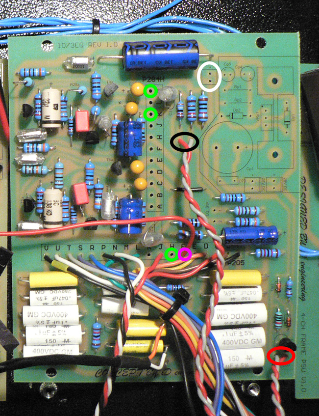
Let's start with the lower (amplifier) board. Solder the LF section wires (pads with names starting with "205_") to the corresponding pads of the P205 connector. Solder wires from the HF potentiometer to the following pads:
Solder wires from the LED to the PWR_LED pads (red circle). Solder wires from pads 182_1 and 182_2 to corresponding pads HPF S4 (black circle). Prepare three wires approximately 10 cm (4") long and solder them to pads "K" and "M" of P284H and to the pad "H" of P205 (green circles). These wires will go to the upper EQ filter board. Solder wire approximately 17 cm (6.7") long to the "F" pad of the P205 (purple circle). This wire will go to the nearby 1290 preamp module. Finally, solder two wires approximately 16 cm (6.3") long to the +24V pads (white circle). These wires will go to the nearby 1290 preamp module power pads. |
 |
|
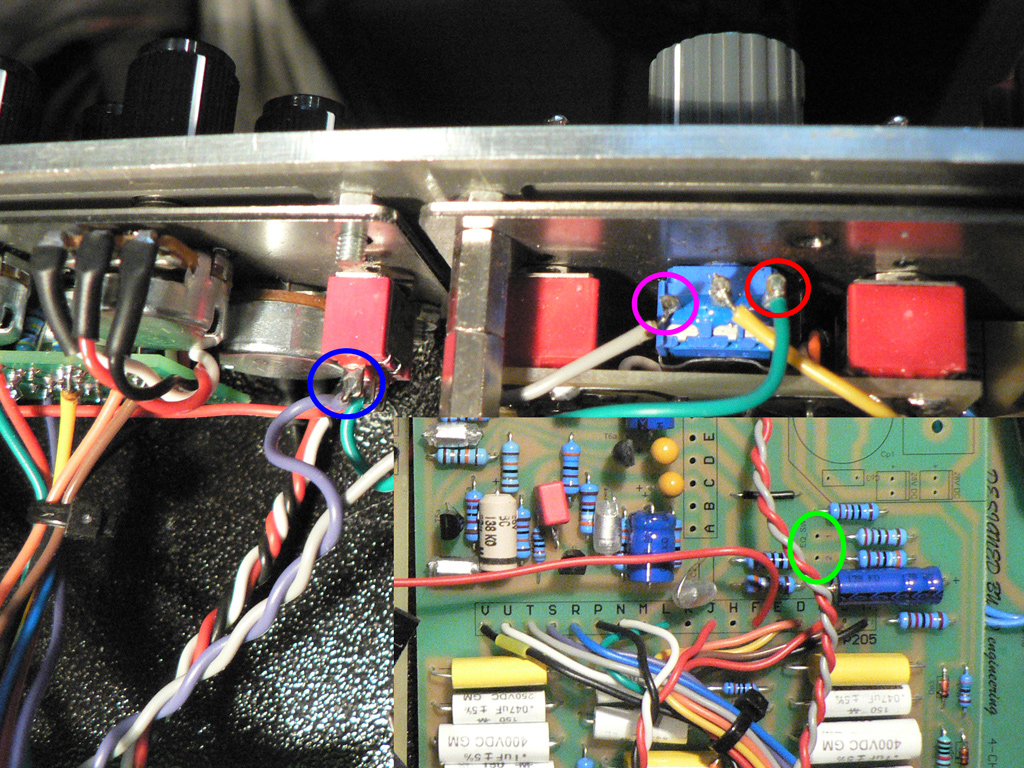
Unsolder wires from CW and CCW pins of the Trim potentiometer on the 1290 module. Prepare two wires approximately 20cm (7.9") long, twist them and solder to the EQ_SW pads of the lower amplifier PCB (green circle). Solder opposite ends of the wire as follows:
Solder a 6 cm (2.3") wire from the common (mid) contact of the EQ switch to the CW contact of the Trim pot. Solder a 10cm (4") wire from the pad 182_3 on the control PCB to the "On" (lower) contact of the EQ switch. |
 |
|
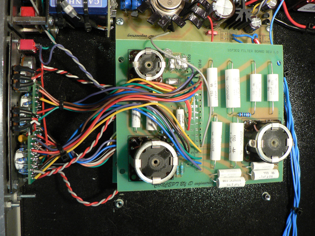
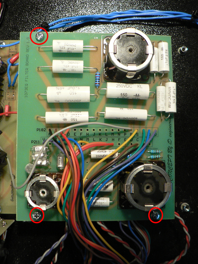
Let's move on to the filter EQ PCB. Solder the Presence section wires (pads with names starting with "211_") to the corresponding pads of the P211 connector. Solder the High pass section wires (pads with names starting with "182_") to the corresponding pads of the P182 connector. Solder 17 cm (6.7") wire to the pad "R" of P182. This wire will go to the 1290 module. Solder wires from the lower amplifier PCB to the following pads (solder wires from the track side of the PCB):
|
 |
|
Finally, solder the wires to the external 1290 module PCB (unpopulated board shown for clarity only, 1290 module must be assembled in order to work properly):
|
 |
|
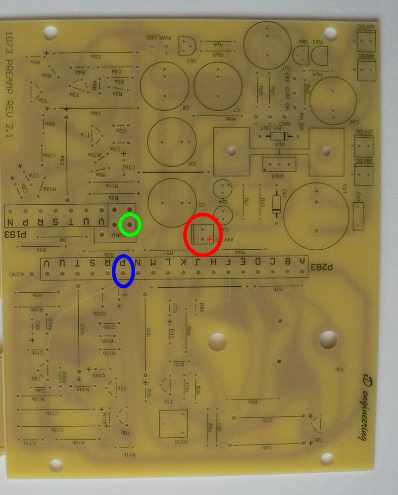
Screw the lower amplifier PCB with three stand-offs in places shown on the photo with red circles. Screw the filter EQ PCB to the stand-offs on top of the amplifier PCB. |
 |
The module is ready. Now it's time to test it.